Full 3D radiation pattern measurement for antennas up to 4.4 GHz — gain, axial ratio, SWR, and beam width. All results delivered as an interactive HTML report you can explore, share, and download.
🏗️ Setup
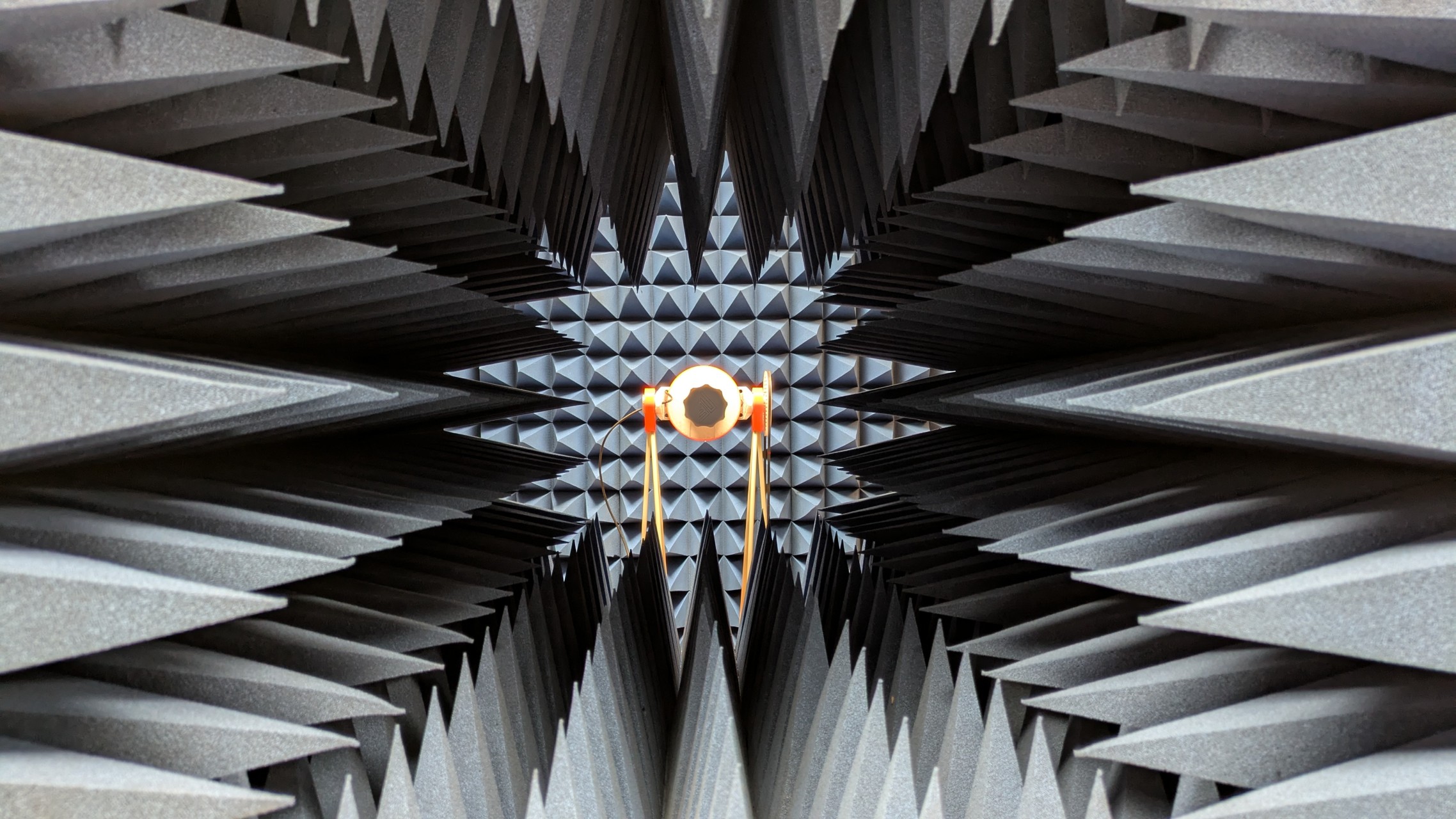
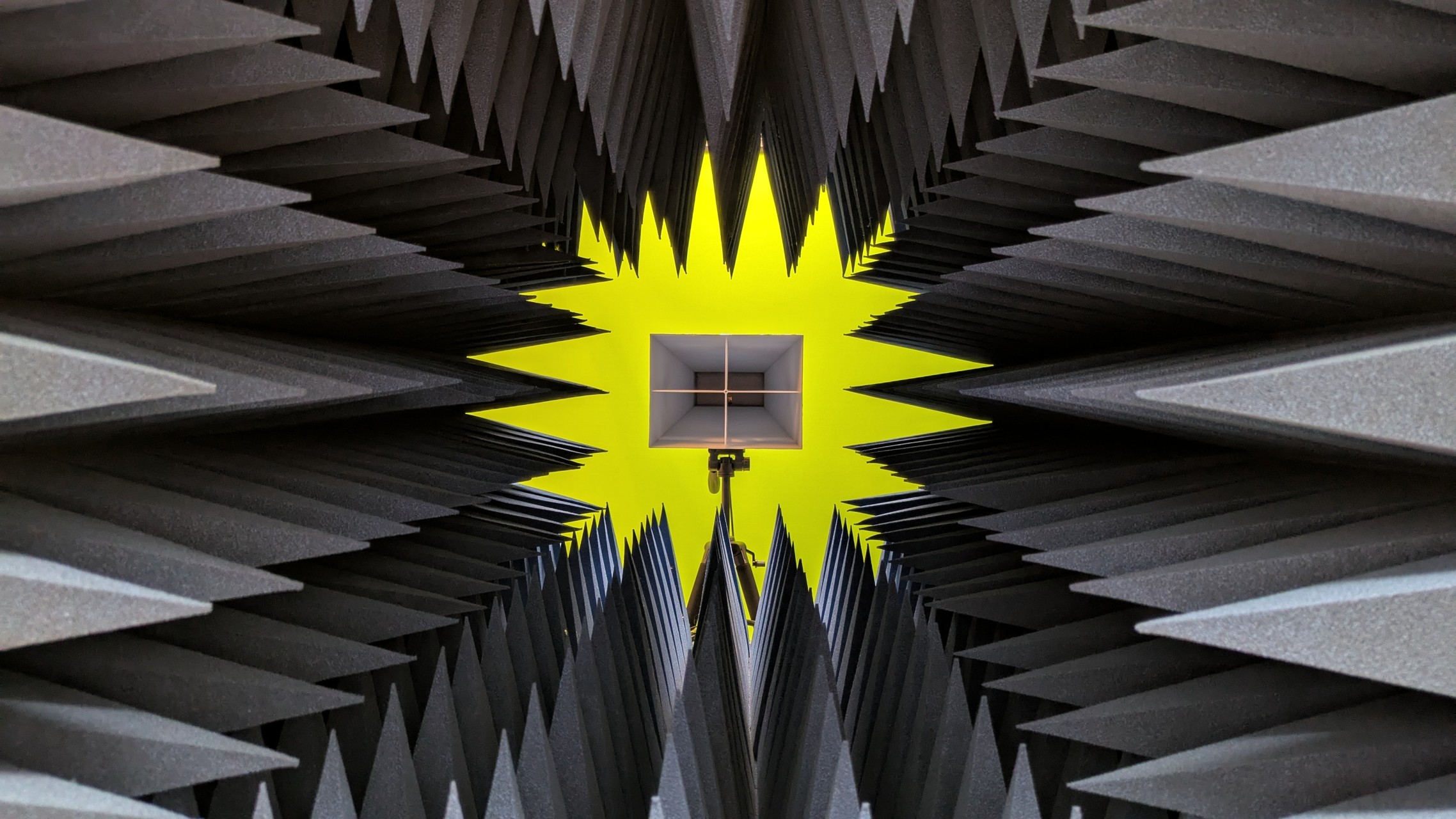
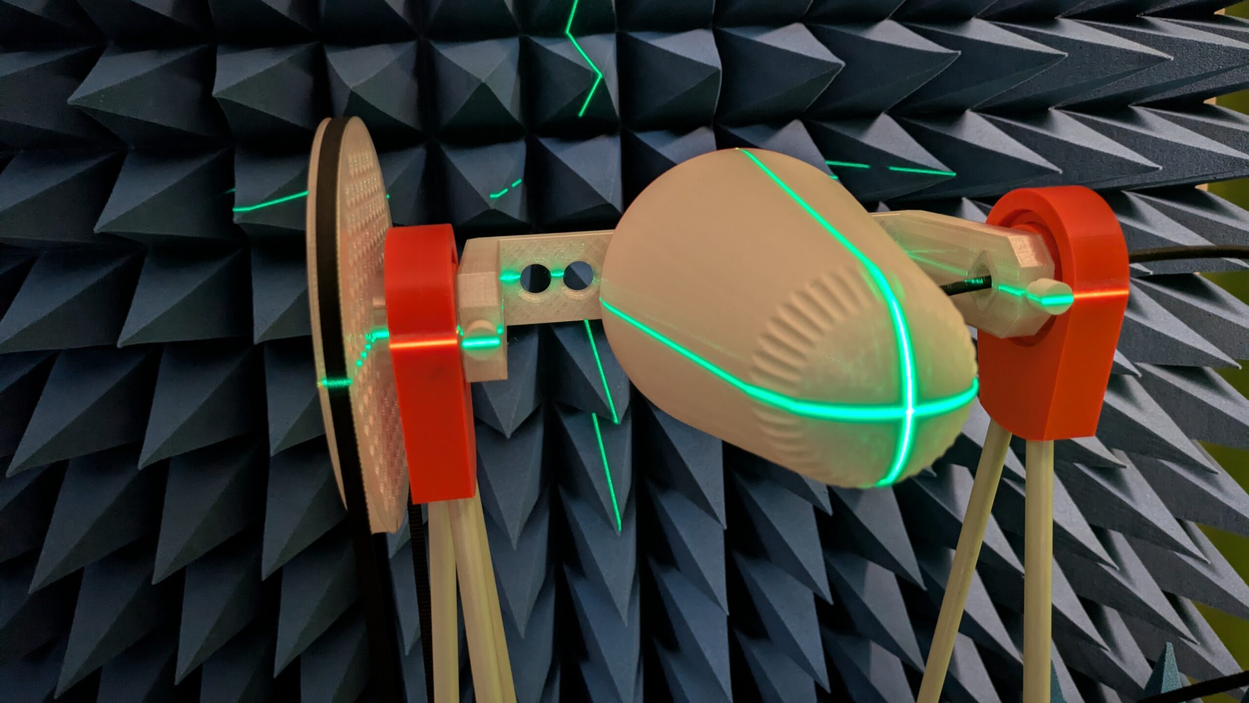
Anechoic measurement field with absorber-lined walls. Full-sphere 3D antenna tracker rotates the antenna under test in elevation and azimuth. Standard gain horn references used for absolute gain calibration — every reading is traceable.
📡 Specification
L, S and C-Band — up to 4.4 GHz. Up to 1000 frequency sweep points per campaign. 1° angular resolution over the full sphere — more than 10,000 measurement points per run.
📋 What You Get
3D gain pattern, 3D axial ratio pattern, 2D gain maps, half-power beam width, SWR and peak gain across the full sweep frequency range — packaged in an interactive HTML report with a 3D visualiser.
🎯 Who Is This For?
Ham radio builders — verify your homebrew antenna actually performs. Compare against simulation. Document gain for your log.
Drone & IoT antenna developers — characterise your product antenna before certification. Catch pattern problems early.
Research & universities — independent measurement data for papers, theses, or grant reports. Repeatable methodology.
Measurement Trajectory & Point Distribution
The antenna tracker does not follow a simple up-down/left-right grid. Instead, it uses a point distribution that spreads measurement samples evenly across the full sphere — so every region of the radiation pattern gets the same angular resolution. A conventional elevation/azimuth scan bunches points near the top and bottom of the sphere and thins out around the equator. Our approach avoids that, producing a cleaner, more complete picture of antenna performance. The traversal order between measurement points is further optimised as a shortest-path problem, minimising total tracker travel and keeping measurement campaigns as short as possible. The plot below shows the measurement point locations and the tracker path — click Traversal Path in the legend to show or hide the path.
Example Test Report
IceConeFeed v2.1 — full 3D gain pattern, axial ratio, SWR and HPBW across frequency. Click to open the interactive report.

Ready to book? The Radiation Pattern Measurement Add-On is available directly in the shop. Add it to your cart to start the process. Contact us at info@nolle.engineering to discuss your antenna and plan the campaign.