The brief was unusual: take an IceConeFeed, retune it to 2490 MHz, mount it underneath an industrial hexacopter, and fly it across the sky — all while a receiver inside a building tries to track it as if it were a satellite 550 km overhead. That is what an ESA-funded S-Band indoor navigation research project asked for, and that is exactly what we built.
Why S-Band Indoor Navigation Needs Non-Standard Frequencies
Standard GNSS signals — GPS L1, Galileo E1 — are designed for unobstructed line-of-sight to open sky. Reinforced concrete, steel structures, and multi-storey buildings attenuate them to the point where a receiver inside cannot get a fix, or loses lock entirely. For emergency responders — firefighters, paramedics, search and rescue teams — this is a real operational problem. Knowing that a colleague is on floor 3, section B, matters when you cannot see or reach them.
One research direction ESA is pursuing — documented in the ESA Navigation Projects portfolio — is using non-standard frequency bands, including S-band (~2.4–2.5 GHz) and VHF, where signal propagation through building materials differs from conventional L-band GNSS. S-band offers a different penetration profile compared to L1/E1, and there is existing LEO satellite infrastructure in that part of the spectrum that could be leveraged for positioning. The question being tested: can you realistically track such a signal from inside a building, and can you derive a usable pseudorange from it?
A custom IceConeFeed for 2490 MHz
The customer needed a transmit antenna that could be mounted on a drone and radiate at 2490 MHz with right-hand circular polarisation — consistent with what a LEO navigation satellite in that band would produce. The IceConeFeed design is inherently frequency-scalable: the conical geometry determines the operating frequency, so customising it to S-band is a matter of modelling the new dimensions and reprinting.
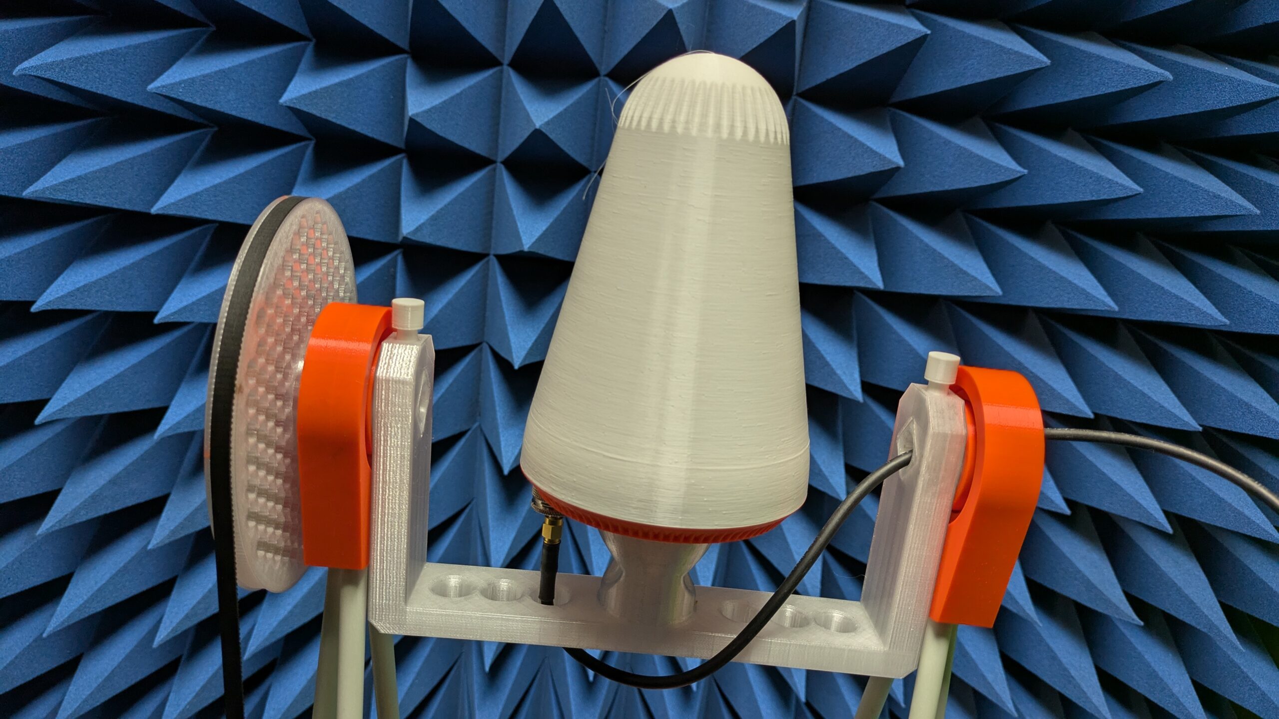
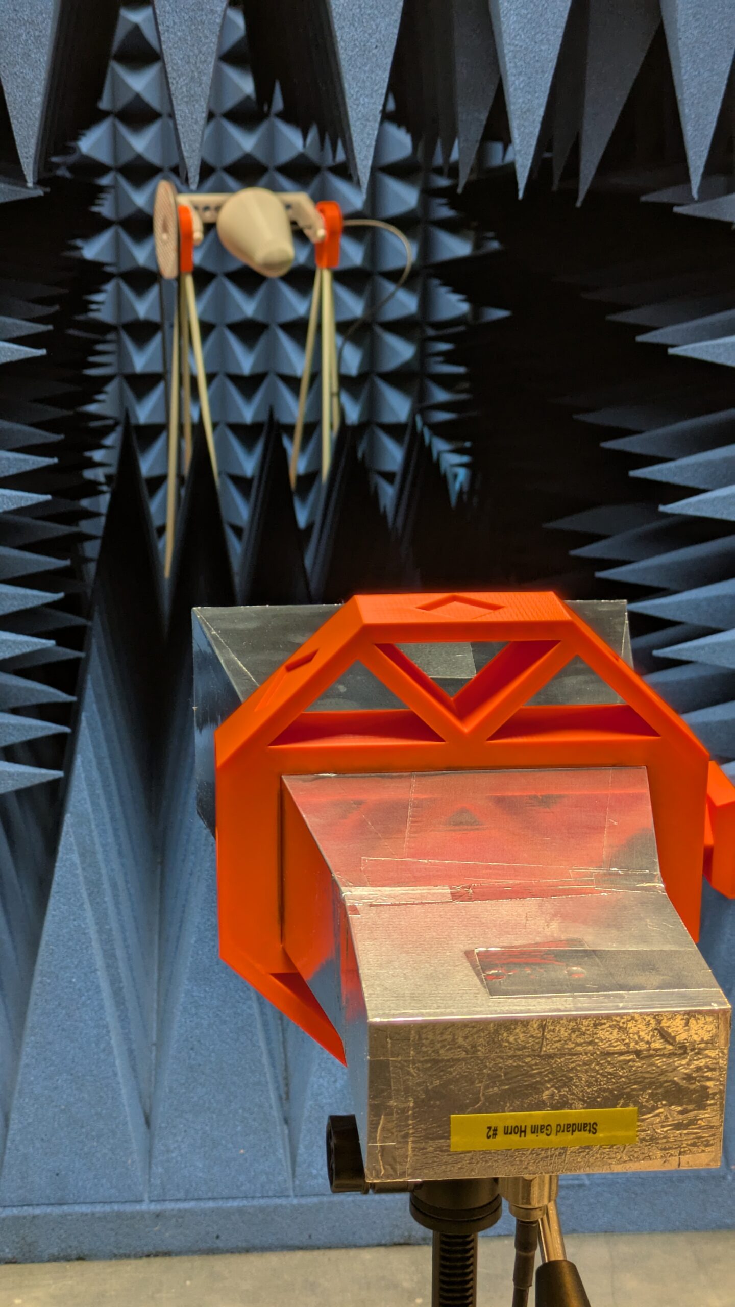
Before the antenna went anywhere near a drone, it went through the Nolle Engineering Antenna Test Facility. We ran a full 3D radiation pattern measurement at 2490 MHz: gain map, axial ratio, SWR. This gave the customer a calibrated reference for what the signal environment looked like from their drone-borne transmitter — essential for interpreting the pseudorange measurements later.
Integration on the drone
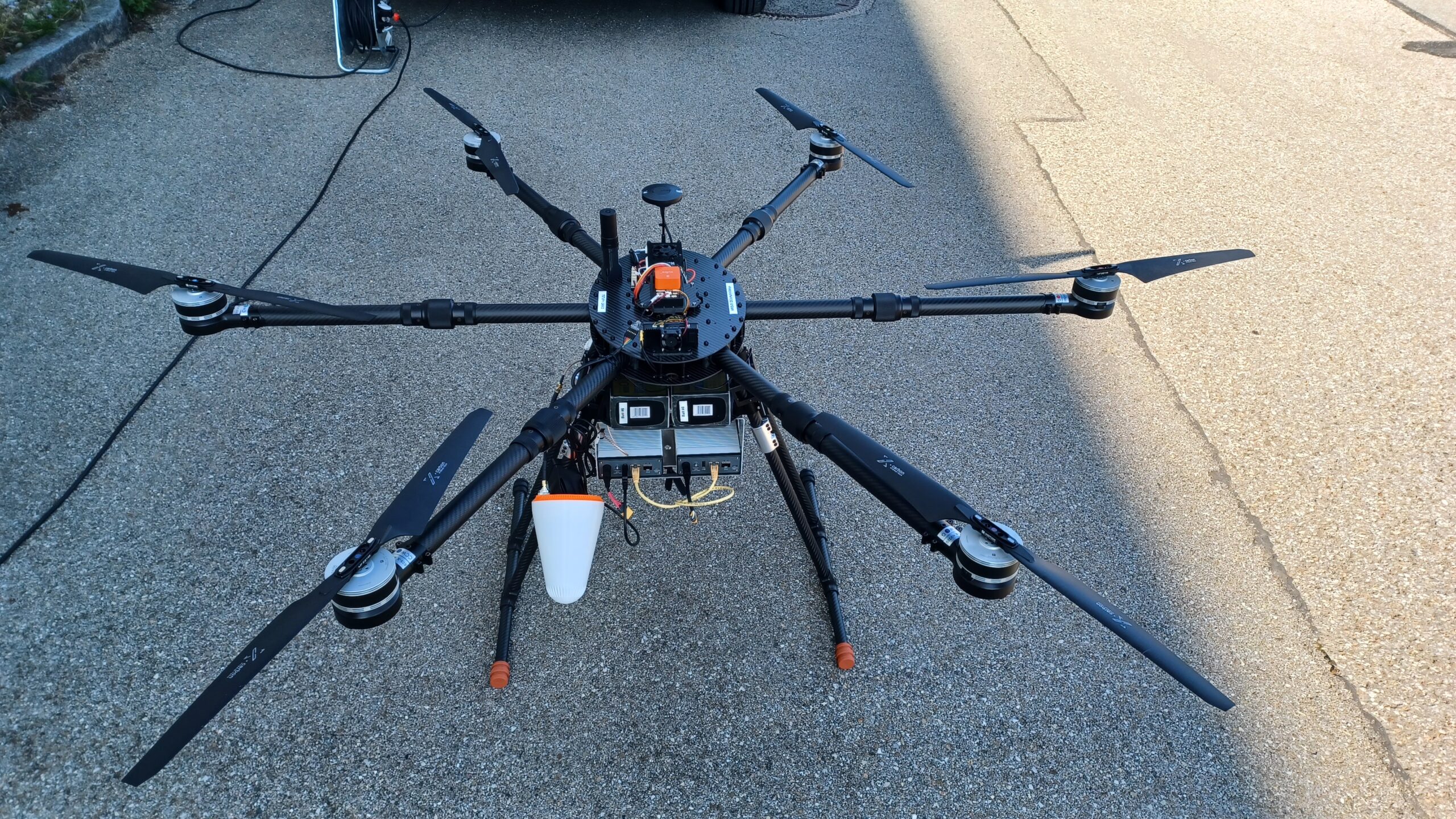
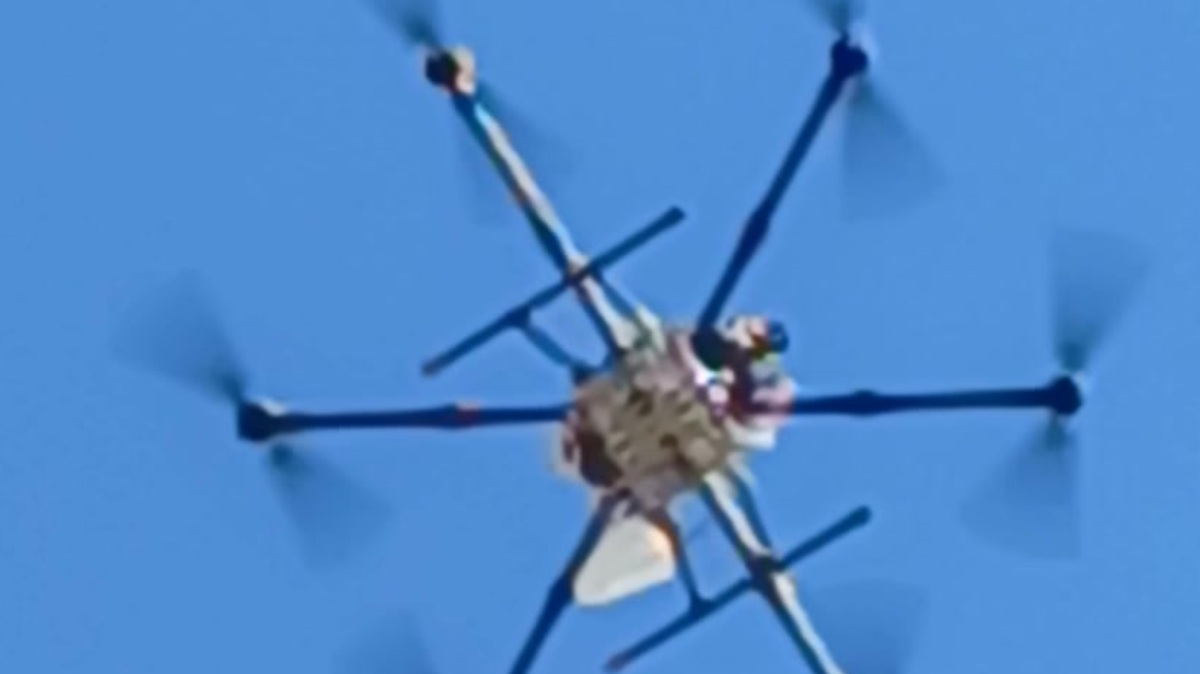
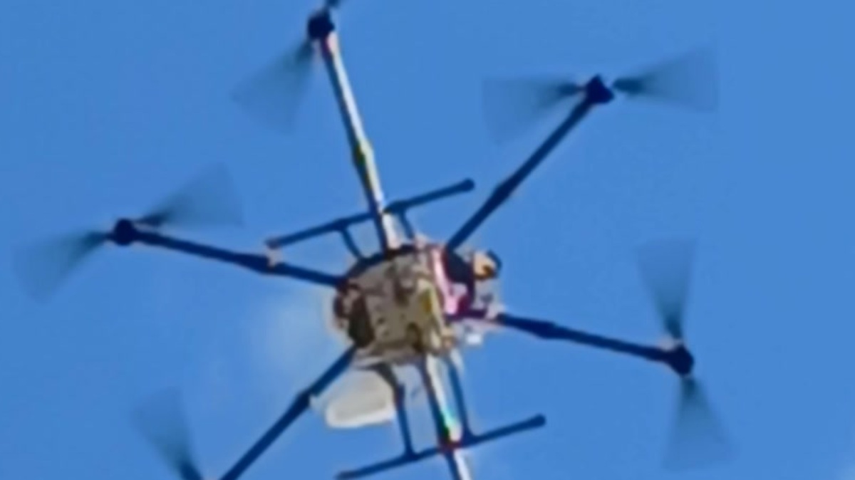
The antenna was integrated under the centre of the hexacopter airframe, angled at 45° elevation — not pointing straight down, but offset to replicate the off-zenith geometry of an actual LEO satellite pass. A real satellite signal arrives at an elevation angle, not from overhead, and the drone flight profiles were designed with that geometry in mind.

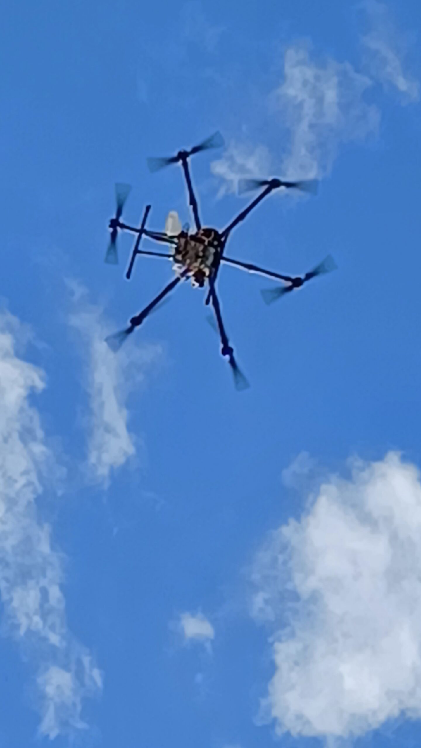
Flying a satellite
The test campaign ran over a full day. The hexacopter flew slow, controlled arcs across the sky above the test building, reproducing the Doppler shift and received power variation that a real LEO satellite pass would generate. The altitude and velocity are much lower than orbital mechanics, but the signal waveform is scaled accordingly — the indoor receiver cannot distinguish a well-crafted drone emulation from the real thing.
Inside the building, the receiver ran a software-defined tracking loop tuned to the S-band signal. At each point in the drone trajectory, it attempted signal acquisition, maintained lock through passes, and derived pseudorange measurements. The quality of those measurements — noise floor, biases, multipath signature — is the dataset the research team needed to assess whether S-Band indoor navigation is viable for emergency positioning.
What This Demonstrates for S-Band Indoor Navigation
This campaign validated two things from a hardware perspective: the custom S-Band IceConeFeed performs as designed in the field, and the Antenna Test Facility produces characterisation data that is directly useful for receiver calibration in real experiments. The measurement report generated before the campaign became a reference the research team used throughout signal processing.
If you are running a research or validation campaign that needs a customised antenna — specific frequency, specific polarisation, with traceable measurement data — the Antenna Test Facility and the IceConeFeed LEO Package are a good starting point.