The Anechoic Test Field is the measurement volume inside the Antenna Test Facility. It is built for antenna characterization — gain, radiation pattern, return loss, axial ratio. Every antenna we manufacture is acceptance-tested here, and customer hardware is measured here during paid campaigns. This page documents the RF layout and the mechanical interface so you can plan what to send.
Layout
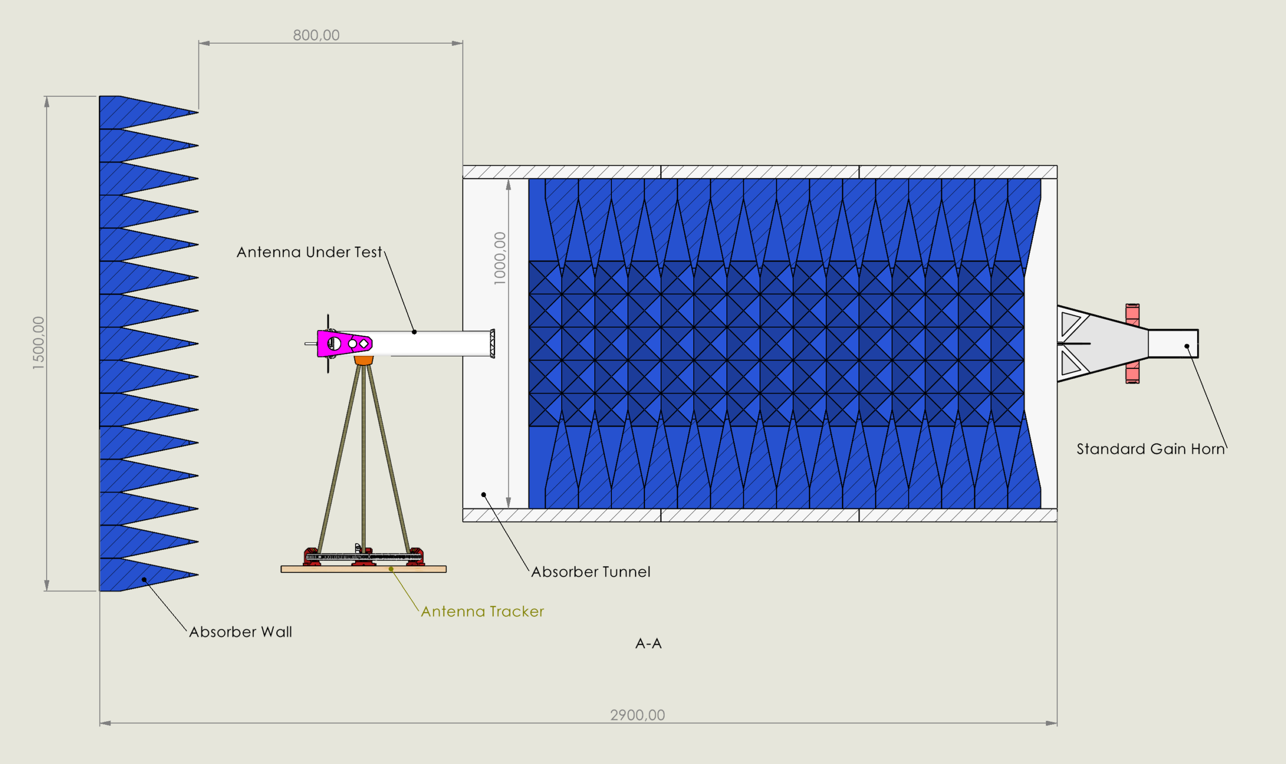
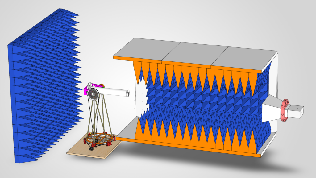
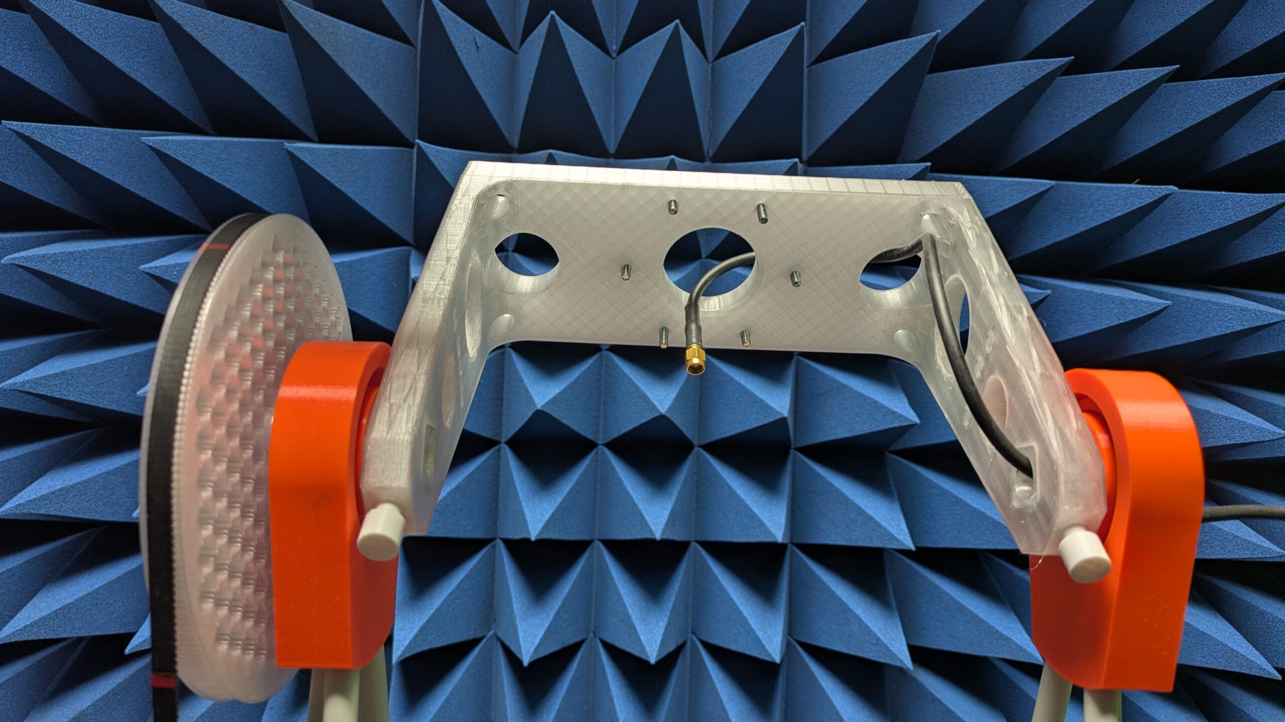
The antenna under test (AUT) sits on a two-axis tracker at the centre of the test field. A wall of pyramidal RF absorbers stands behind it. A linearly polarised standard gain horn sits at the far end of an absorber-lined tunnel, pointing back at the AUT.
- Back wall — absorbers behind the AUT terminate all rearward radiation.
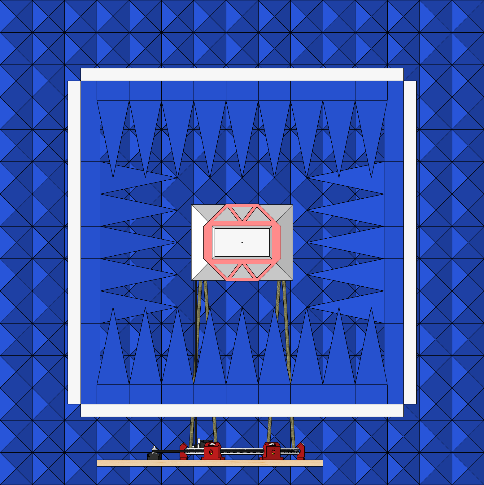
- Tracker — two-axis positioner (azimuth + elevation). The AUT phase centre sits on the intersection of the two rotation axes, so the AUT rotates in place rather than orbiting.
- Tunnel — absorber-lined channel from the AUT plane to the standard gain horn. It sets the receive field of view: anything outside the tunnel mouth is invisible to the horn, and off-axis room reflections strike absorber before they reach it.
- Standard gain horn — fixed at the far end of the tunnel, linearly polarised. Each measurement is two complete sphere sweeps — one with the horn vertical, one horizontal. Power integrated over the full sphere sets the absolute scale; the vertical and horizontal components combine in post-processing to give the AUT pattern (dBi for linearly polarised AUTs, dBic for circularly polarised) and the axial ratio across the pattern. No separate calibration step required.
Absorber specification
The back wall and the tunnel walls share the same absorber: a carbon-loaded polyurethane pyramidal foam with fire-retardant treatment.
| Parameter | Value |
|---|---|
| Geometry | Pyramidal, 5 × 5 pyramids per 500 × 500 mm panel |
| Total height | 300 mm (60 mm flat base + 240 mm pyramid) |
| Pyramid base | 100 × 100 mm |
| Material | Carbon-loaded polyurethane foam |
| Operating range | 80 MHz – 100 GHz |
Normal-incidence reflectivity, manufacturer’s published values:
| Frequency | Maximum reflectivity |
|---|---|
| 1 GHz | −15 dB |
| 1.5 GHz | −28 dB |
| 3 GHz | −38 dB |
| 5 GHz | −45 dB |
| 10 GHz | −50 dB |
| 15 GHz | −50 dB |
| 40 GHz | −50 dB |
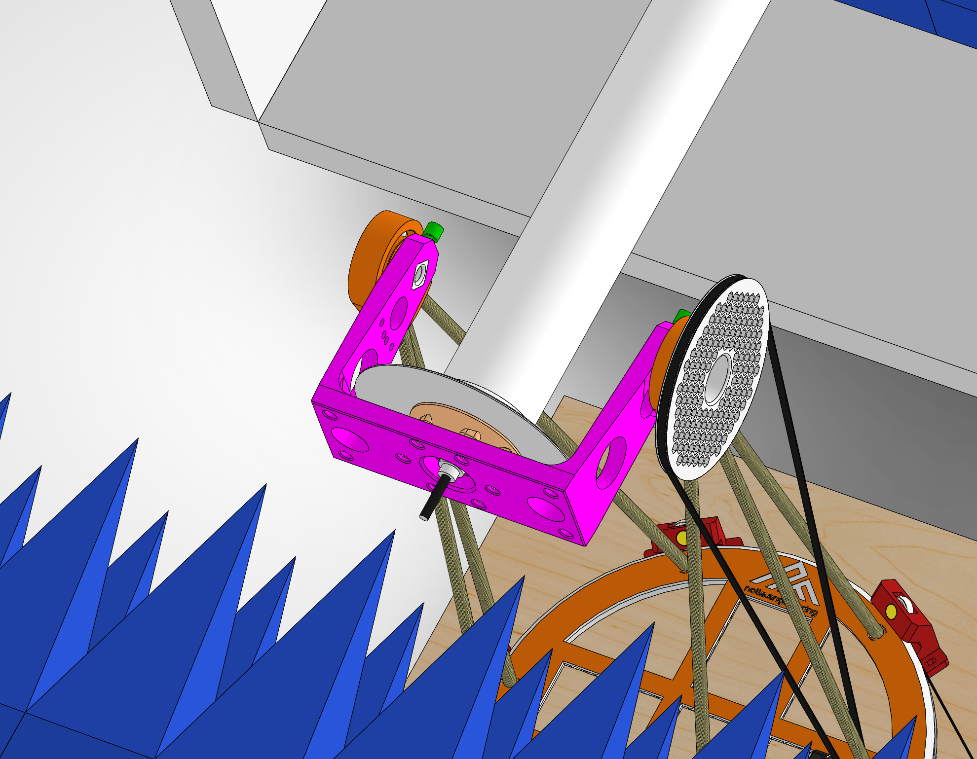
Antenna mount and tracker interface
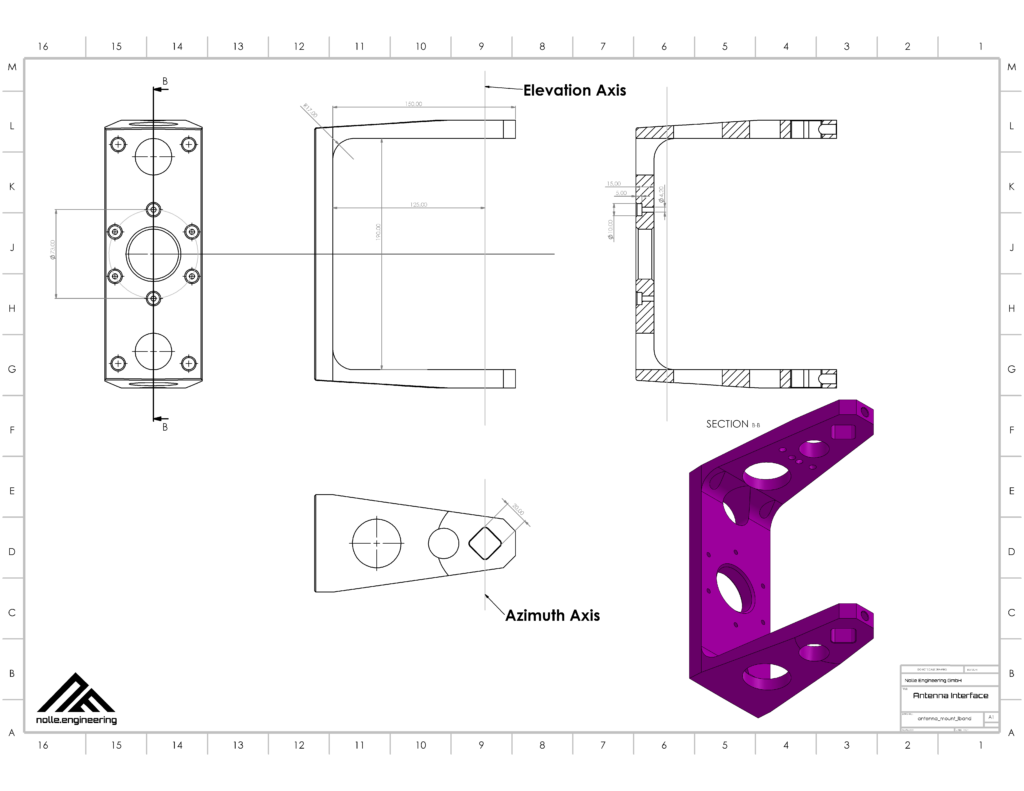
The AUT mounts to a 3D-printed C-bracket carried by the tracker. The bracket rotates about the elevation axis at one end and about the azimuth axis at the other; this places the AUT phase centre on the intersection of the two rotation axes.
Mechanical envelope
Before sending an antenna for measurement, confirm the following against your design:
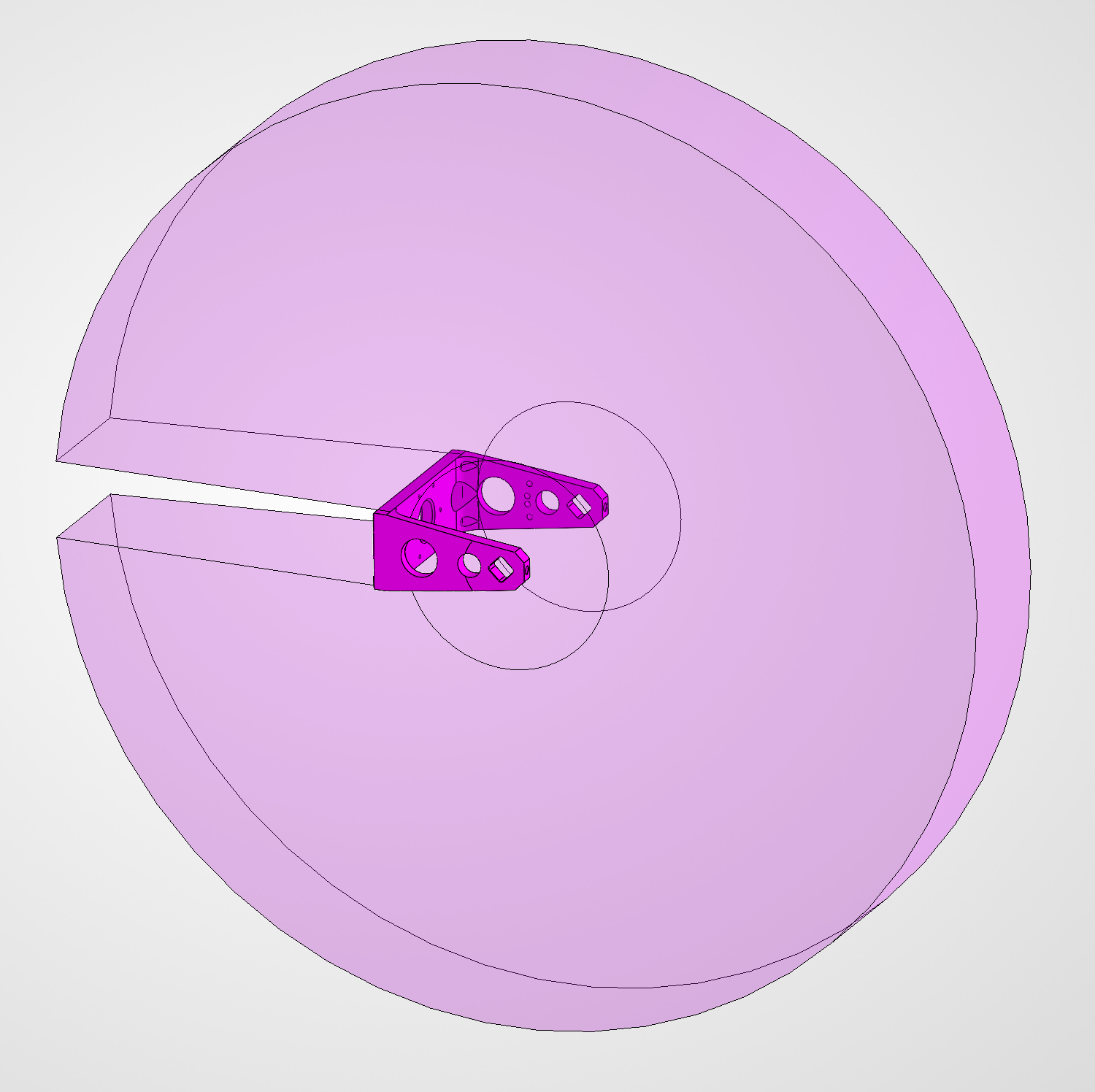
- Maximum AUT envelope — the swept-volume envelope that fits between the bracket arms and clears the tunnel mouth during a full sphere sweep is shown below and supplied as a STEP model alongside the bracket interface (Adapter design files).
- Maximum mass / inertia — validated for an L-Band helix baseline: 650 g total, 0.068 kg·m² about the elevation axis. Higher on request.
- Mounting interface — bolt-circle and pin pattern per the bracket drawing above.
- RF interface — SMA on the bracket. Adapters available for other connector families; specify in the booking.
RF parameters — frequency coverage, polarization handling, dynamic range, achievable pattern resolution — live on the Antenna Test Facility page.
Adapter design files
One STEP file contains two objects: the standard mounting bracket interface and the maximum AUT mechanical envelope. Use the bracket as the reference geometry when designing an adapter for an antenna that does not match an existing bracket variant, and use the envelope to verify your antenna fits inside the swept volume.
Need a custom adapter? Share the antenna footprint and we can design and print the adapter as part of the booking. Talk to us.