
This page looks at receiving the Iridium L-band downlink with one of our helix antennas on a fixed mount, and at which direction to point it. We simulated the pass geometry from current orbital elements and compared the result with SatNOGS recordings. Where the numbers are uncertain we say so.
Iridium in brief
Iridium is a low-earth-orbit constellation of 66 active satellites in six near-polar planes (86.4° inclination, about 780 km altitude, roughly 100 minutes per orbit). There is no fixed satellite to aim at, so a dish or tracking is not an option for a simple station. The user downlink is 1616–1626.5 MHz, RHCP. Each satellite covers the ground with 48 spot beams. Ring-alert and broadcast bursts are sent at constant power; traffic bursts are power-controlled. With a fixed antenna the question is how much of the sky it covers, and how much time satellites spend in that part of the sky.
Where the satellites are
Because the orbit planes converge near the pole, a station at 48° N sees most of the satellite time at low elevation and toward the north. About 78 % of the visible satellite time is below 30° elevation. Overhead passes occur but are short.
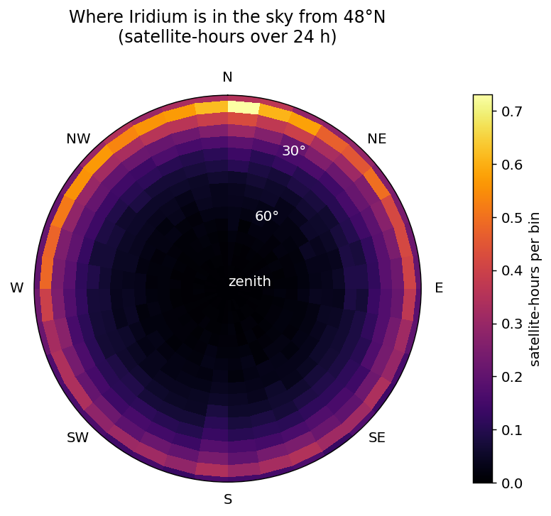
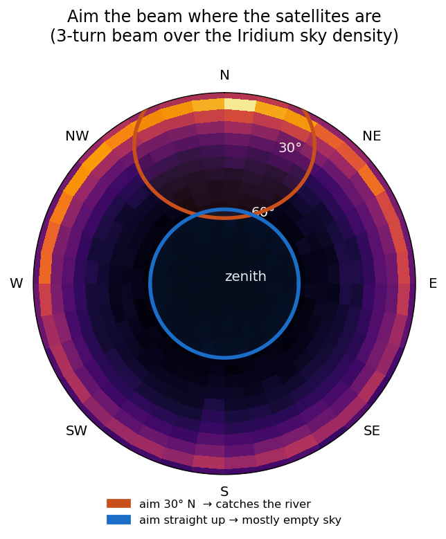
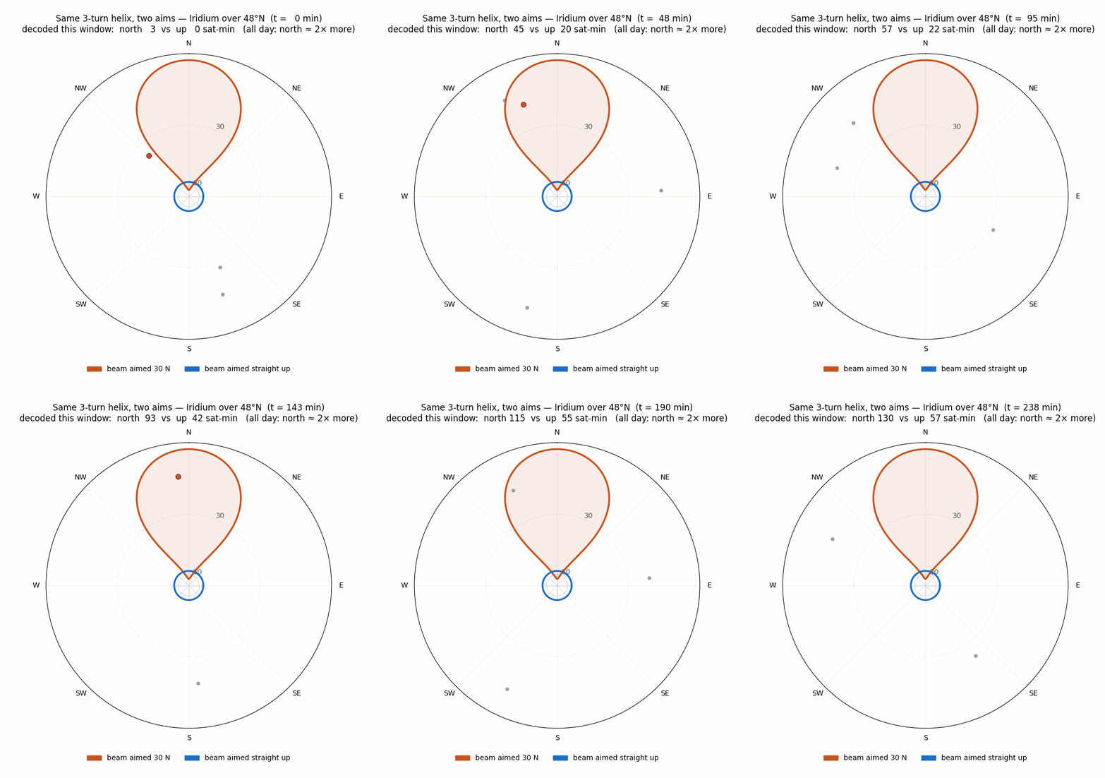
A helix pointed at the zenith therefore covers the part of the sky with the fewest satellites. Tilted down toward the north, the main beam covers the region where they spend most of their time.
Recommended pointing
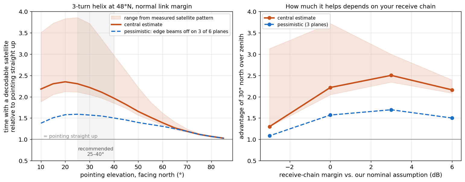
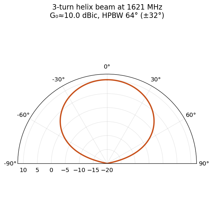
For our 3-turn RHCP helix (half-power beamwidth about 64°) on a fixed mount: about 30° elevation, facing north. 25–40° gives nearly the same result, and the azimuth is not critical within 30–45° of north. With a weak receive chain (long coax, no preamp at the antenna) or obstructions to the north, 40–45° is the better choice. Most of the improvement comes from the tilt itself; facing north adds a smaller amount.
Expected improvement
In the simulation (current elements, SGP4, 24 h, 48° N, satellite power pattern fitted from the SatNOGS data), the tilted helix has at least one decodable satellite in view 1.5 to 2.5 times as often as the same helix pointed at the zenith, and the longest gaps between usable passes are much shorter. The figure depends on the link margin of the station, which we cannot know in advance. With a marginal setup the improvement is about 1.1–1.3×. In none of the cases we ran was zenith pointing better.
Comparison with SatNOGS recordings
We analysed 1035 waterfall recordings of Iridium satellites from 26 SatNOGS stations between 30° and 64° N, about 51 000 ten-second samples, each tagged with the satellite position at that time.
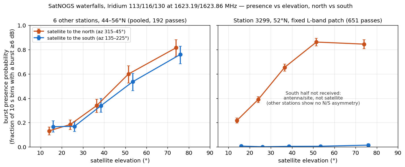
- At the same elevation, satellites to the north and to the south show the same burst activity within the error bars. The data give no indication that the northern satellites serve mid-latitude users less well.
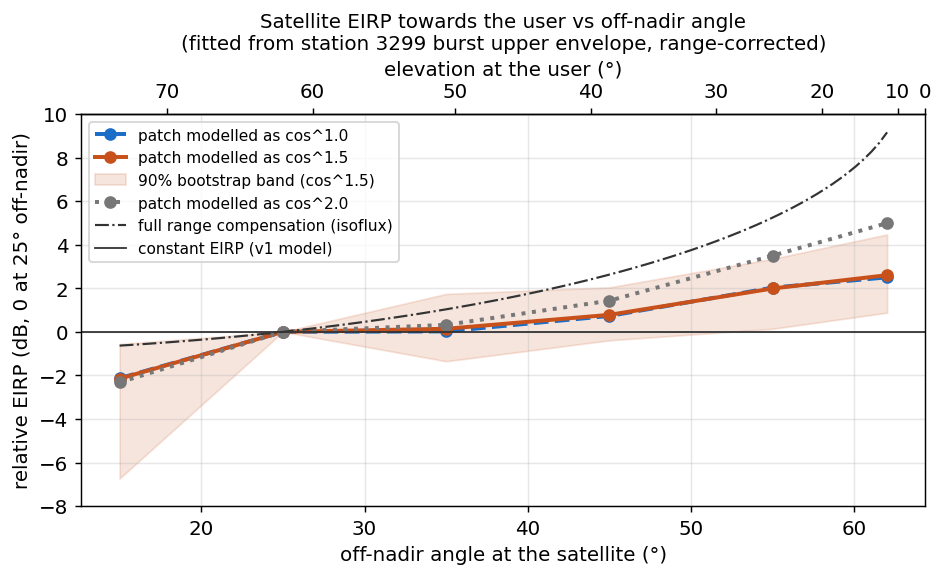
- The satellite power toward low-elevation users is about 1 to 5 dB higher than toward users near the sub-satellite point. This compensates part of the additional path loss, not all of it; the downlink is not isoflux.
- One station in the Netherlands receives only the northern half of the sky, apparently due to its antenna mounting. It logged bursts in about 85 % of the samples for satellites between 50° and 75° elevation in the north.
Antenna
Standard axial-mode helix, circumference one wavelength, 12.5° pitch, wound RHCP and tuned for 1616–1626 MHz. The Kraus formula gives about 10 dBic for three turns; a real unit is closer to 8–9 dBic, and the simulation uses 8.5 dBic. We also modelled a 2-turn version with a wider beam. It does not do better than three turns once the antenna is tilted.
Open points
- All recordings come from three satellites in the same orbital plane. Iridium switches off some edge beams at high latitudes on part of its planes, which we could not check. With edge beams off on three planes, the model still gives about 1.6× for north pointing (1.1× with marginal link).
- The decode threshold of a real station is the largest uncertainty. We plan an on-air comparison (same helix and SDR, alternating days at zenith and 30° north) and a pattern measurement of the 3-turn helix on our test range, and will add the results here.
Method
80 current Iridium-NEXT element sets (Celestrak), propagated with SGP4 over 24 h in 10 s steps for 48.1° N, 8° horizon mask. Helix modelled as a cos^q main lobe matched to its beamwidth. Satellite EIRP versus off-nadir angle fitted from the SatNOGS burst levels, with a bootstrap band; decode threshold varied by ±3–6 dB around a nominal value. Ratios between pointings are more reliable than absolute coverage figures. Waterfall data: SatNOGS Network (Libre Space Foundation), CC BY-SA 4.0.
Decoding
For decoding we refer to iridium-toolkit (CCC Munich) with gr-iridium or iridium-sniffer as the demodulator. It decodes ring alerts, paging and messaging, ACARS and, with an AMBE vocoder, voice. It needs an SDR covering 1616–1626 MHz and runs on Linux.
Nolle Engineering, October 2026.