Specification
All parts 3D printed from PETG material, UV resistent and water proof.
| LHCP | RHCP-7 | RHCP-10 | |
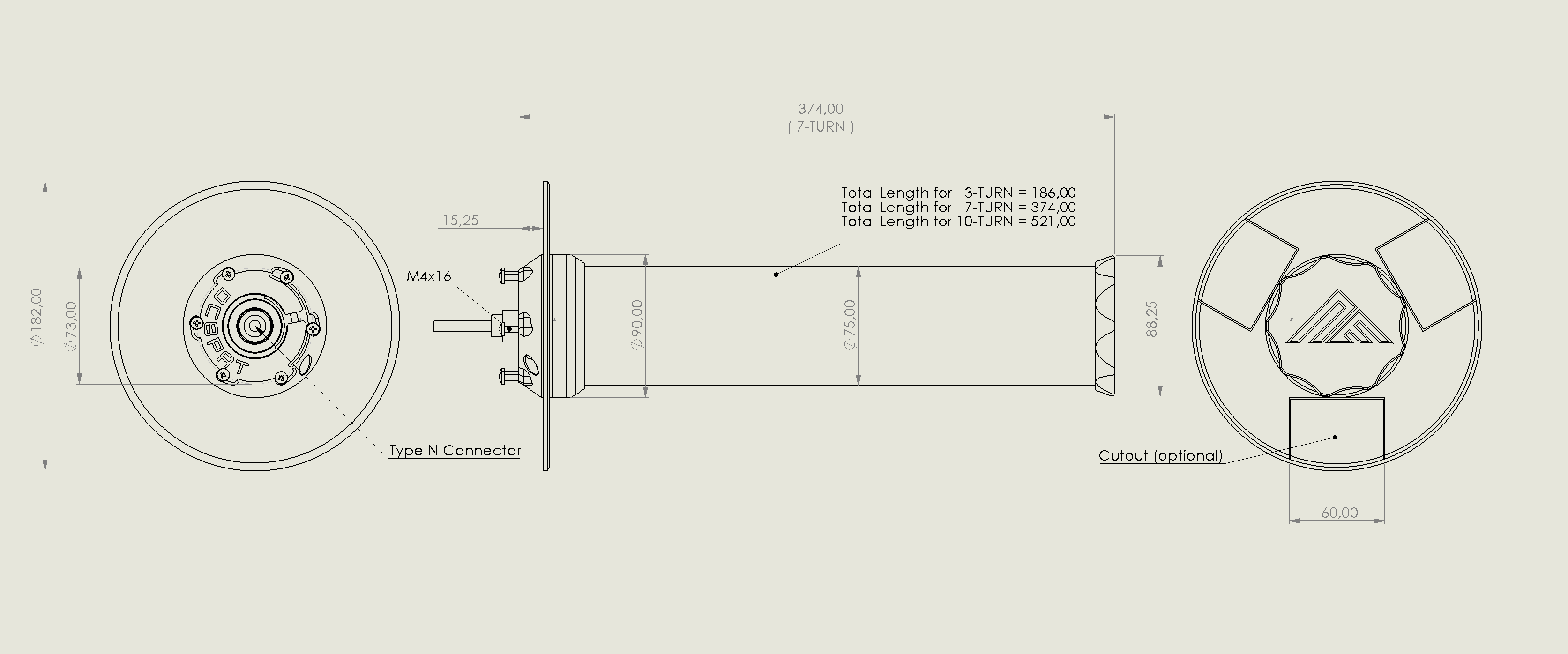
| Radiating Element | 3 turn left handed helix, 3.5mm copper wire | 7 turn right handed helix, 3.5mm copper wire | 10 turn right handed helix, 3.5mm copper wire |
| RF Performance | Measurement Report | ||
| Reception configuration | TV satellite dish | Direct reception | Direct reception |
| Mounting Option | Mounts in standard 40mm LNB clamp (for offset dishes) Universal mounting via 3-6 M4 bolts (for prime focus dishes) | Universal mounting via 6 M4 bolts | Universal mounting via 6 M4 bolts |
| Dimensions | Length: 186mm Diameter: 180mm | Length: 374mm Diameter: 180mm | Length: 521mm Diameter: 180mm |
| Weight | 289 g | 510 g | 650 g |
| Connector | N-type | N-type | N-type |
| Applications | Reception of geostationary satellite services, e.g. Inmarsat, Iridium, digital telephony / data, digital weather pictures | Reception of geostationary and LEO satellites when mounted to el/az-rotor | Reception of geostationary and LEO satellites when mounted to el/az-rotor Higher gain for low elevation GEO |
| Availability | LHCP | RHCP (7 turn helix option) | RHCP (10 turn helix option) |
| CAD Model | lband_step_files | lband_step_files | lband_step_files |

Mounting Options


L-Band station example
Architecture
See below an example on how to setup your L-Band receiver station. Signal is filtered, amplified and digitized by software defined radio then provided to software receiver running on your local PC.
Filtering is optional, it might be necessary depending on your local RF environment (Wifi, LTE presense).

Assembly and components list
Click on the image below to navigate to the assembly instructions of the RHCP variant:

Decoder Software
A list of popular INMARSAT and others deconding software packages:

Web SDR Demo
Web SDR working Inmarsat-4 (Alphasat) 25 East and Inmarsat-3 54 West from grid square JN58UA using L-Band RHCP 7 turn and 10 turn helix antenna respectively.
Click on the image below to go to the live WebSDR
